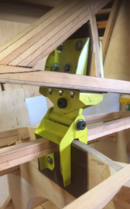
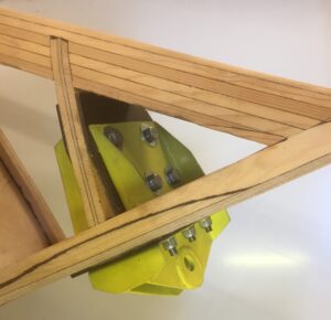
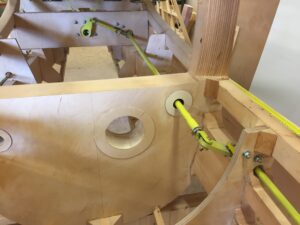
Vertical stabiliser forward fuselage attachment
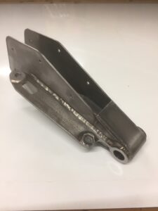
The vertical stabiliser forward attachment brackets are completed and installed. The next building step will be the attachment of the vertical stabiliser spar to the
The vertical stabiliser forward attachment brackets are completed and installed. The next building step will be the attachment of the vertical stabiliser spar to the
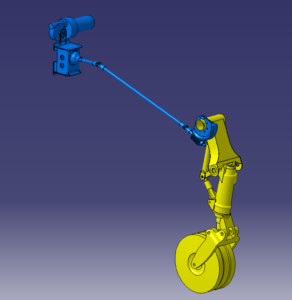
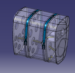
The drawing of the nose landing gear and its mechanical components on CAD took me several weeks. The gear retraction and extention is actuated through
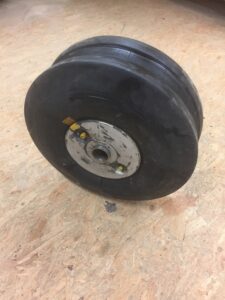
A spontaneous visit to a Venom owner paid out. The wheel was hidden away in a dark basement for decades. Fortunately the owner was prepared
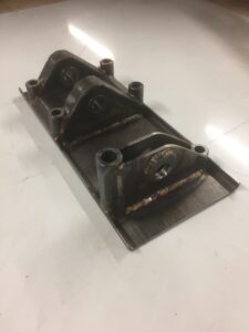
Manufacturing the base attachment plate proved to be a real challenge. Cutting out and bendig each metal part took hours of pure handwork. In order
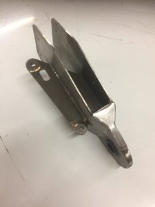
Countles liters of Argon, several feet of welding wire plus one dull milling cutter, the second bracket is completed.
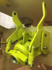
The first bracket for the vertical fin mount is completed. It took me a full four days of intensive metalwork and welding, reject included. Note
The front attachment of the vertical stabiliser is built of three parts, each made of welded CrMo sheet metal.
Not much building progress in the past few weeks but instead some headway in respect of engineering. I spent a few weeks under the warm
There are two pivoting links and three control rods connecting the mixing unit with the angled shaft in the rear of he fuselage. To make
The assembly of the gear took considerably longer than expected. The conical bolts for the crossbar can not be found on this side of the